
Flightcase PDUs · TTPF Series
TTPF125-001
Rated current
125A
IP rating
IP54
Input
Protection
CEE 125A 5PMCCB + VMR
Outputs
Protection
8× Socapex48× RCBO
3× auxiliary3× RCBO
Price on request
View & Configure 
125A Plastic PDU · CEE 125A 5P input · 8× Socapex · 3× auxiliary
Input
Protection
Outputs
Protection
Price on request
Built for high-capacity lighting distribution
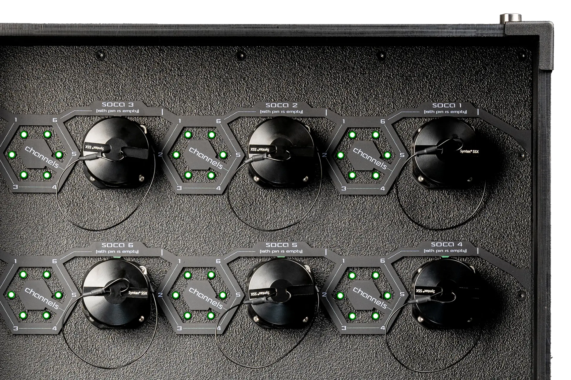
Socapex multicore connections carry six power circuits through a single cable and are widely used for stage lighting, LED systems and temporary production setups.
TTP125-001 combines eight Socapex outputs with individual RCBO protection for all 48 circuits, plus three configurable auxiliary outputs, in a compact, stackable IP54 HDPE enclosure.
Integrated power and voltage monitoring, emergency shutdown and independently powered diagnostics give crews the visibility and control required for large professional productions.
Technical information
Explore complete product data, features, functionality, mechanical and electrical design, environmental ratings, compliance, configuration options and documentation.
Product data
| Input | Input Protections |
|---|---|
| 1× CEE 125A 400 V 5P (Mennekes) | 1× Main MCCB 125A 4P Icn: 25 kA with extended rotary handle (Siemens) |
| 1× Voltage monitoring relay, VMR (Schneider Electric) |
| Outputs | Output Protections |
|---|---|
| 8× Syntax® SSX 16A 230V 19P with IP67 protective cap (Valentini) | 48× RCBO C16A 30 mA 1P A-type (Siemens) |
| 3× Auxiliary outputs, 230 V 3P, with selectable connector type | 3× RCBO C16A* 30 mA 1P A-type (Siemens) |
| 1× HAN® GND grounding connector (Harting) | Not applicable |
*For selected auxiliary connectors, the rated current of the RCBO varies. The J1 version is fitted with an RCBO C10A 30 mA 1P A-type; the G1 and B1 versions are fitted with an RCBO C13A 30 mA 1P A-type.
Features
Functionality
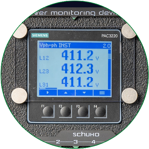
Real-time power data, where you need it.
The integrated Siemens PAC3220 monitors voltage, current, power and energy consumption through three current transformers. Two panel-mounted Ethernet connections provide network access. Measurements can be viewed through the device’s built-in web interface on the same network without additional software, while Modbus TCP supports integration with compatible monitoring systems.
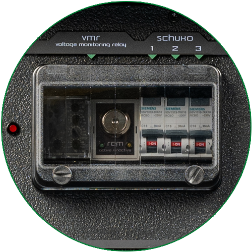
Continuous voltage supervision.
The phase-to-neutral voltage monitoring relay detects phase loss, missing neutral, overvoltage and undervoltage. When a critical fault is detected, it can initiate an alarm or disconnect the power supply. A secure key-operated bypass allows qualified personnel to temporarily override the VMR during controlled diagnostic or maintenance procedures.
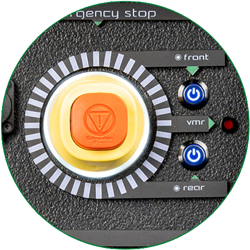
Immediate shutdown when it matters.
The front-mounted emergency stop can immediately disconnect all outputs through the shunt-trip release of the main MCCB. Monitoring systems, diagnostic tools and working lights remain operational through independently protected circuits, supporting rapid fault identification and intervention.
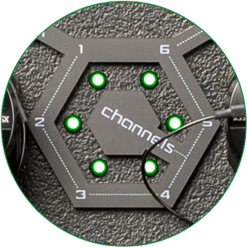
Clear status at a glance.
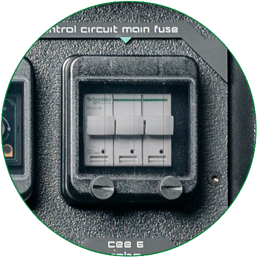
Diagnostics remain available after a trip.
Power monitoring, voltage monitoring, emergency functions, working lights and their indicator LEDs are supplied through independently fused circuits. If the main MCCB trips, these systems remain active to support fault identification and maintain diagnostic visibility.
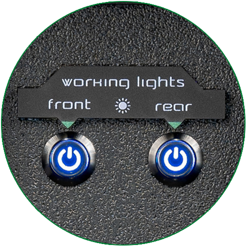
Built for low-light working environments.
One front and one rear working light, controlled through front-panel pushbuttons, improve visibility during setup, operation and maintenance backstage or on site.
Design
| Design Item | Specification |
|---|---|
| Ingress Protection | IP54-rated enclosure with transparent hinged covers for the MCCB, RCBOs and VMR, providing dust protection and resistance to water splashes in semi-outdoor or protected outdoor environments. |
| Enclosure Material | Constructed from high-density polyethylene with a structured surface. The HDPE is UV-stabilised and water-resistant, providing mechanical strength, long-term durability and resistance to environmental stress. |
| Handles | Two heavy-duty industrial-grade handles for safe and ergonomic transport. |
| Feet | Eight stainless steel stacking feet provide wear resistance and support stable vertical stacking during storage and transport. |
| Aluminium Corners | Rugged welded aluminium corners protect the enclosure edges against impact and wear during repeated handling, transport and operation. |
| Overall Dimensions | 725 x 525 x 555 mm, Height x Width x Depth |
| Labelling | All connectors and protective devices are identified with UV-printed markings resistant to UV exposure and solvent-based cleaning agents. |
| Connector Installation | Quick Connector Replacement system. Connectors are mounted with four stainless steel screws and sufficient internal cable slack to allow replacement without dismantling the complete enclosure. |
| Internal Conductor Cross-Sections | 125A circuits: 50 mm² Cu. 16A circuits: 2.5 mm² Cu. |
| Internal Cabling | Helukabel flexible conductors, H07V-K or equivalent. |
| Terminal Blocks | Phoenix Contact or Ouneva spring-cage or screw-type terminals, selected according to application and load class. |
Electrical
| Specification | Value |
|---|---|
| Rated Voltage | 400 V AC, 3P+N+PE |
| Rated Current | 125A |
| Frequency | 50/60 Hz |
| Maximum Continuous Load | 86 kVA, 86 kW at cos φ = 1 |
| Rated Diversity Factor | 0.46 |
| Rated Conditional Short-Circuit Current | 25 kA according to EN 60898 |
| Protection Class | Class I, protective earth |
Maximum continuous load is specified at an ambient air temperature of 30 °C.
Environment
| Rating | Value |
|---|---|
| Operating Temperature | −25 °C to +40 °C, with the average ambient temperature over a 24-hour period not exceeding +35 °C (in accordance with IEC/EN 61439 recommendations). |
| Storage Temperature | 0 °C to +40 °C |
| Relative Humidity | Maximum 100% from −25 °C to +27 °C, decreasing to 60% at +35 °C and 46% at +40 °C, non-condensing, in accordance with IEC/EN 61439 recommendations |
| Maximum Installation Altitude | 2,000 m above sea level |
Compliance
| Category | Details |
|---|---|
| CE Compliance | Components and final assemblies are CE marked and compliant with the applicable EU directives, including the Low Voltage Directive 2014/35/EU and EMC Directive 2014/30/EU. |
| Standards Compliance | EN 61439-1: Low-voltage switchgear and controlgear assemblies, General rules. EN 61439-4: Assemblies for construction sites. |
| Manufacturer Information | Tesla Entertainment Kft., H-1151 Budapest, Károlyi Sándor út 158., Hungary. EU VAT ID: HU26587255. |
| Country of Origin | Hungary. All units are assembled and tested at the Tesla Tech facility in Budapest. |
Configuration
Select the right connection for your market. All auxiliary outputs use the selected connector type.
| Code | Type | Rated Current | IP Code | Manufacturer |
|---|---|---|---|---|
| F1 | German / Austrian (Type F) | 16A | IP54 | Mennekes |
| F2 | German / Austrian with gasket (Type F) | 16A | IP54 | Mennekes |
| E1 | French / Belgian (Type E) | 16A | IP44 | Mennekes |
| G1 | British (Type G) | 13A | IP44 | ABL |
| P1 | powerCON TRUE1 with sealing self-closing cap | 16A | IP65 | Neutrik |
| J1 | Swiss T13 (Type J) | 10A | IP54 | PCE |
| J2 | Swiss T23 (Type J) | 16A | IP54 | PCE |
| B1 | USA / Canada (Type B) | 15A | IP44 | ABL |
| K1 | Danish (Type K) | 16A | IP44 | PCE |
| CE | CEE 6h | 16A | IP54 | Mennekes |
The stated IP rating applies when all enclosure lids and covers are fully closed. When connectors are mated, the overall ingress protection level depends on the IP rating of the connected plugs.
Documentation
PDF · EN
PDF · EN
PDF · EN
PDF · EN
Product information on this webpage is provided for guidance and may contain errors or omissions. Always refer to the latest downloadable product documentation for the definitive technical specifications and instructions.
Related products
Compare alternative products and explore PDUs, breakout units and cable assemblies for your setup.
Flightcase PDUs · TTPF Series
Rated current
125A
IP rating
IP54
Input
Protection
Outputs
Protection

Flightcase PDUs · TTPF Series
Rated current
400A
IP rating
IP54
Input
Protection
Outputs
Protection

Modular PDUs · TTMM Series
Rated current per channel
16A
IP rating
IP65
Input
Protection
Outputs
Protection

Modular PDUs · TTMM Series
Rated current
16A
IP rating
IP65
Input
Protection
Outputs
Protection

Multipin Cables
Socapex Cable Assemblies

CEE Cables
Mennekes Black CEE 125A 5P Cable
Request a quote
Send us your requirements and we will confirm the right TTP configuration or engineer one for your application.