
CUSTOM POWER SOLUTIONS
ENGINEERED AROUND THE COMPLETE POWER GRID.
We begin with the complete application: the power source, connected loads, distribution structure, operating environment and workflow.
Then we define the right combination of standard and custom distribution, protection and cable infrastructure.
STANDARD WHERE POSSIBLE. ENGINEERED WHERE NECESSARY.

SYSTEM ENGINEERING
THE RIGHT SOLUTION STARTS WITH THE WHOLE GRID.
Before designing an individual unit, we understand how power needs to move through the complete application.
We review the available power source, connected loads, distribution points, cable distances, environmental conditions and operational requirements. Based on this, we recommend the distribution architecture and protection levels required across the grid.






MAIN DISTRIBUTION
Receives power from the source and provides the primary distribution and protection for downstream circuits.
INTERMEDIATE DISTRIBUTION
Redistributes power closer to individual production areas, departments or technical systems.
FINAL DISTRIBUTION
Provides the final power connections close to individual devices or groups of equipment.
CABLE INFRASTRUCTURE
Connects every distribution level through the appropriate cable assemblies, connectors and adapters.
PROTECTION STRATEGY
DESIGNED TO KEEP A LOCAL FAULT LOCAL.
Protection is not selected independently for each box. The different protection levels must work together across the complete power grid.
We coordinate upstream and downstream protection around the actual loads and operating conditions so that the required selectivity can be designed and verified.

COORDINATED PROTECTION
MCBs, MCCBs, RCCBs and RCBOs selected and coordinated for their position within the distribution structure.

FAULT ISOLATION
The protection architecture is designed to contain faults as close as possible to their source while allowing unaffected parts of the grid to continue operating.

VISIBILITY AND CONTROL
Voltage monitoring, status indication and remote monitoring can be integrated where the application requires greater operational visibility.
STANDARD AND CUSTOM
ONLY AS CUSTOM AS THE APPLICATION REQUIRES.
A fully custom product is not always the best solution. We first identify where existing Tesla Tech products meet the requirements and engineer new elements only where necessary.

STANDARD PRODUCT
An existing TTPF, TTP, TTM or TTMM configuration or standard cable assembly already meets the technical and operational requirements.

MODIFIED STANDARD
A proven Tesla Tech design is adapted through different connections, protection, monitoring, internal layout or identification.
FULLY CUSTOM SOLUTION
The enclosure, mechanical design, electrical architecture and internal layout are developed specifically for the application.
The objective is the most effective solution for the complete grid, not the most complicated one.
PROCESS
FROM REQUIREMENTS TO A FINISHED SOLUTION.
- 01
UNDERSTAND THE APPLICATION
We begin with what the equipment needs to do, where it will be used and how the production team will operate it.
- 02
MAP THE COMPLETE POWER GRID
We review the power source, loads, connection points, cable distances, indoor or outdoor conditions and operational workflow.
- 03
DEFINE THE DISTRIBUTION ARCHITECTURE
We recommend the required main, intermediate and final distribution units, together with the cable infrastructure connecting them.
- 04
COORDINATE THE PROTECTION LEVELS
We define the protection concept, fault isolation, monitoring and selectivity requirements across the distribution structure.
- 05
DEVELOP AND ITERATE THE SOLUTION
We refine the technical configuration, connections, internal layout and external design with you through several review rounds.
- 06
MANUFACTURE, TEST AND DOCUMENT
Following final approval, the equipment is manufactured, assembled and tested in Budapest. The required technical documentation is prepared for the completed solution.
ENGINEERING SCOPE
BUILT AROUND YOUR REQUIREMENTS.
From a modified standard unit to a completely new power distribution solution, each element can be developed around the application.
ENCLOSURE AND FORMAT
Flightcase, plastic, rack-mounted, modular or purpose-built mechanical formats.
INPUTS AND OUTPUTS
Connector types, ratings, quantities, positions and cable interfaces selected around the equipment being supplied.
PROTECTION ARCHITECTURE
Main and individual circuit protection developed around the loads and the required distribution hierarchy.
MONITORING AND DIAGNOSTICS
Status indication, voltage monitoring, energy measurement and remote monitoring where required.
INTERNAL LAYOUT
Electrical and mechanical layouts designed for safe operation, clear servicing and efficient use of space.
IDENTIFICATION AND FINISH
Labelling, colour-coded connectors, front-panel layout and visual details adapted to the customer’s workflow.
CABLE ASSEMBLIES
The corresponding power, multicore, bonding and adapter cables can be supplied as part of the complete system.
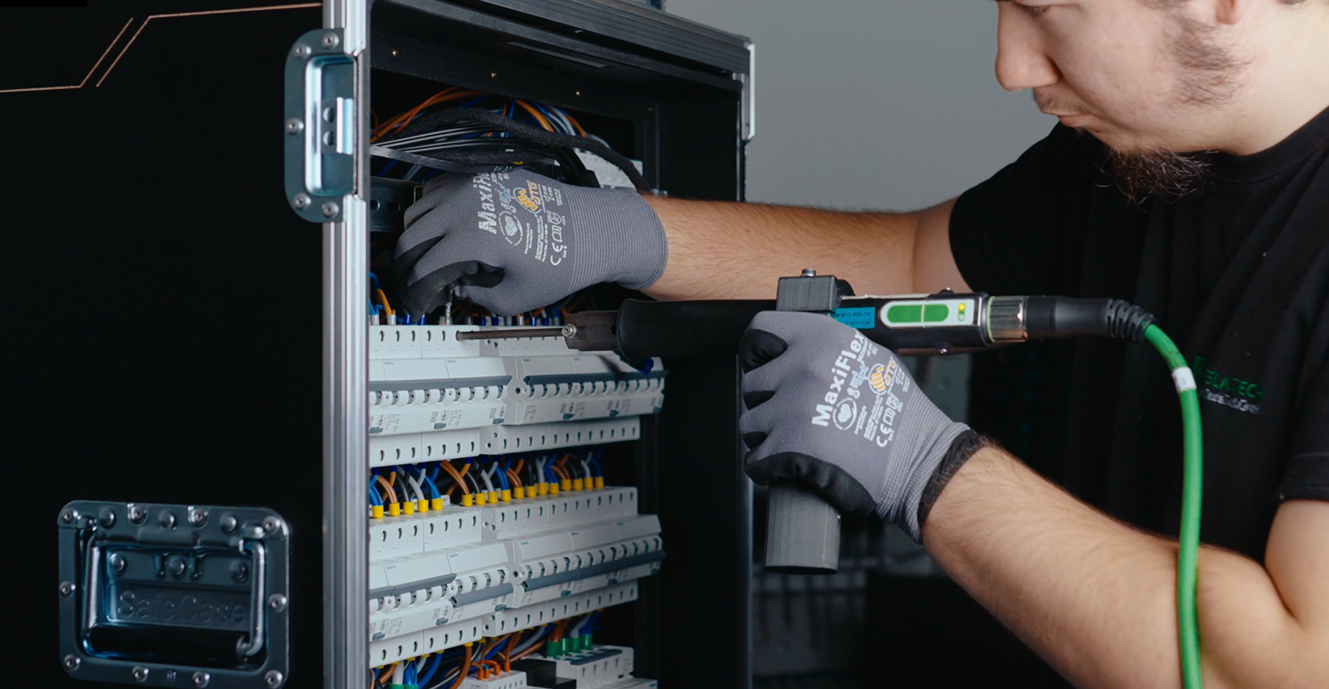
MANUFACTURED IN BUDAPEST
DESIGNED. ASSEMBLED. TESTED.
Once the final configuration has been approved, the product is manufactured and tested in-house in Budapest for demanding professional use.
PREMIUM COMPONENTS
Components are selected from established professional manufacturers according to the technical requirements of the application.
IN-HOUSE PRODUCTION
The electrical design, assembly and testing remain under Tesla Tech’s control throughout the project.
TESTED BEFORE DELIVERY
The completed equipment is inspected and tested against the approved technical configuration.
TECHNICAL DOCUMENTATION
The documentation package is defined for each project and may include a technical specification, single-line diagram, user manual and CE declaration of conformity, as applicable.
START YOUR PROJECT
TELL US WHAT THE EQUIPMENT NEEDS TO DO.
You do not need to have a finished technical design.
Tell us what the equipment needs to do, where it will be used and what it needs to connect to. Our engineers will review the information and help define the next step.