
KNOWLEDGE CENTER
PROTECTION 101.
Understand what each device does, which faults it responds to and why it matters in a live production.
A power distribution unit brings together devices with different jobs. Some disconnect a faulty circuit. Others monitor the supply and provide a warning or trigger a shutdown. This guide explains the main protection and monitoring functions, with practical examples from event production.
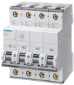
01 · MCB
MCB
MINIATURE CIRCUIT BREAKER
An MCB disconnects a circuit when an overload or short circuit causes excessive current. Its main purpose is to protect the circuit’s cables and conductors.
HOW IT WORKS
An overload occurs when equipment draws more current than the circuit is designed to carry for too long. A short circuit occurs when a fault creates an unintended low-resistance connection, allowing a much higher current to flow.
A typical MCB uses a thermal mechanism to respond to sustained overloads and a magnetic mechanism to respond rapidly to high short-circuit currents. Its current rating and trip characteristic determine how it responds.
WHY IT MATTERS
An MCB helps prevent excessive current from overheating cables and damaging the installation. The device must be selected to suit the cable, load and available fault current.
An MCB provides overcurrent protection. An RCCB or RCBO provides the residual current protection explained below.
AT AN EVENT
Several additional appliances overload a backstage supply, and its MCB disconnects the circuit to limit overheating of the cable.
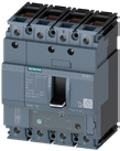
02 · MCCB
MCCB
MOULDED CASE CIRCUIT BREAKER
An MCCB provides overload and short-circuit protection for distribution circuits. Many models offer adjustable protection settings to suit the application.
HOW IT WORKS
Like an MCB, an MCCB detects excessive current and opens the circuit. Its trip unit is the mechanism that detects the fault and initiates opening; depending on the model, it uses thermal-magnetic or electronic protection.
MCCBs are commonly used at main supplies and larger outgoing circuits. Selection depends on the current to be carried, the fault current the device may need to interrupt and the required protection settings.
WHY IT MATTERS
An MCCB protects a major distribution circuit and can support coordination with downstream breakers. On adjustable models, the protection settings can be matched to the circuit and its position within the grid.
The aim of coordination is to let the appropriate device clear a fault while limiting unnecessary disconnection elsewhere. The selected devices and settings must be checked against the manufacturer’s coordination data.
AT AN EVENT
A damaged feeder develops a short circuit between two live conductors, and the MCCB protecting that feeder disconnects its supply.
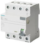
03 · RCCB
RCCB
RESIDUAL CURRENT CIRCUIT BREAKER
An RCCB disconnects a circuit when it detects a residual current above its operating threshold. This helps reduce the risks associated with current flowing through an unintended path to earth.
HOW IT WORKS
An RCCB belongs to the RCD family. RCD stands for Residual Current Device, a general term that also includes RCBOs.
The RCCB monitors the balance of current in the circuit’s live conductors. If some current returns through another path, such as protective earth, the imbalance is detected as residual current.
When the device’s operating conditions are met, it disconnects the circuit. The appropriate residual current type, sensitivity and operating time depend on the installation and connected equipment.
WHY IT MATTERS
Insulation damage and moisture can create leakage paths that an ordinary overcurrent device may not detect at the required level. Residual current protection addresses this different type of fault.
An RCCB works alongside overcurrent protection. Its ampere rating indicates the current it can carry, rather than an overload trip setting.
AT AN EVENT
Moisture creates an earth-leakage fault in an outdoor lighting circuit, and the RCCB disconnects the supply when its operating threshold is reached.
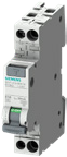
04 · RCBO
RCBO
RESIDUAL CURRENT CIRCUIT BREAKER WITH OVERCURRENT PROTECTION
An RCBO combines residual current, overload and short-circuit protection in one device. It is particularly useful for protecting individual outgoing circuits.
HOW IT WORKS
An RCBO monitors both the amount of current flowing through the circuit and any residual current imbalance. It can therefore respond to an overload, a short circuit or an earth-leakage fault.
Its overcurrent characteristic and residual current specification must both suit the circuit and the equipment being supplied.
WHY IT MATTERS
Individual RCBOs give each outgoing circuit its own combined protection. This makes the affected circuit easier to identify and can reduce the number of loads disconnected by a local fault.
Keeping the rest of the distribution operating also depends on coordination with upstream protection.
AT AN EVENT
In a correctly coordinated lighting distribution, an earth-leakage fault in one fixture trips its circuit’s RCBO while the other lighting circuits remain supplied.
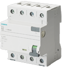
05 · SELECTIVE RCCB
SELECTIVE RCCB
SELECTIVE RESIDUAL CURRENT CIRCUIT BREAKER
A selective RCCB introduces a controlled delay to help downstream residual current protection operate first. It supports a protection strategy that limits the spread of an interruption.
HOW IT WORKS
An earth-leakage fault downstream can be detected by more than one residual current device along the supply path.
A selective upstream device allows a coordinated downstream device time to clear the fault. If the fault remains, the upstream device can operate according to its own characteristics.
WHY IT MATTERS
This coordination is called selectivity. Its purpose is to disconnect the affected circuit while keeping unrelated circuits available.
Selectivity depends on the combination of device types, residual current thresholds and operating times. A delayed device alone does not guarantee it, and an upstream selective RCCB does not replace the final-circuit protection required by the installation.
AT AN EVENT
A fault on one lighting branch is cleared by its downstream RCBO, while the coordinated selective RCCB keeps the supply to the other branches connected.
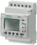
06 · RCM
RCM
RESIDUAL CURRENT MONITOR
An RCM continuously monitors residual current. In our PDU configurations equipped with RCM, it also triggers automatic disconnection when the configured fault conditions are met.
HOW IT WORKS
The RCM measures the current imbalance in the monitored circuit. When the configured threshold and response time are reached, it activates its output to initiate disconnection through the connected switching or tripping device.
Depending on the configuration, it can also provide an earlier warning, helping operators identify developing leakage conditions before the shutdown threshold is reached.
WHY IT MATTERS
Residual current monitoring provides visibility of leakage conditions, while the integrated shutdown function allows the system to respond automatically to a fault.
Adjustable thresholds and response times allow the arrangement to be coordinated with the application and other protective devices. These settings form part of the engineered protection design.
AT AN EVENT
Earth leakage rises on an outdoor video supply, and the RCM triggers the connected trip device to disconnect it when the configured shutdown conditions are met.
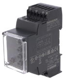
07 · VMR
VMR
VOLTAGE MONITORING RELAY
A VMR monitors the supply voltage and detects specified abnormal conditions. When integrated with a suitable switching or tripping device, it can initiate disconnection of the affected supply.
HOW IT WORKS
The relay compares the measured supply conditions with its configured limits. Depending on the model, it can monitor overvoltage, undervoltage, phase loss or loss of the neutral conductor.
When it detects a qualifying fault, its output changes state. A connected contactor or circuit-breaker trip mechanism then performs the power disconnection.
WHY IT MATTERS
Electronic equipment needs a supply voltage within its operating limits. A loose or broken neutral in an unbalanced three-phase system can cause damaging phase-to-neutral voltages at connected single-phase loads.
A suitable VMR and shutdown arrangement can reduce exposure to these conditions. The protection depends on the monitored fault, settings and response time; a VMR does not regulate the voltage or replace surge protection.
AT AN EVENT
A loose neutral causes abnormal voltages on an LED-wall supply, and a suitable VMR detects the fault and triggers disconnection to reduce the risk of equipment damage.
THE RIGHT PROTECTION WORKS AS A SYSTEM.
Each device has a specific role. Reliable distribution depends on selecting and coordinating those roles around the power source, cables, connected equipment and operating environment.
Our engineers can help define the protection and monitoring functions required for your application.
This guide explains general principles and uses illustrative event scenarios. Device capabilities vary by model and configuration. Protection selection, settings and installation must be assessed by a qualified electrical professional in accordance with the applicable requirements.